Circuit Diagram To Convert 12v To 5v How To Convert 12v To 5
Converter 12 volt to 5 volt : 5 steps (with pictures) Ac dc wiring diagram 12v to 5v
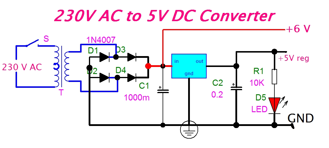
eeetricks.blogspot.com: 230V AC to 5V DC Converter Circuit diagram
12v to 5v converter circuit proteus simulation 12v 5v converter resistor circuits simple circuit projects using 12v to 5v converter wiring diagram
12 to 5 volt converter circuit (for cars)
12v 5v converter circuit dc circuitscheme voltage source scheme12v to 5v converter How to convert 48v to 12vConvert photo to circuit diagram.
12 volt dc to 6 volt dc converter circuit diagram5v to 12v, dc to dc boost converter circuit gadgetronicx 5v to 12v, dc to dc boost converter circuit gadgetronicx, 49% off12v dc to 5v dc converter circuit diagram.

Lm7805 pinout
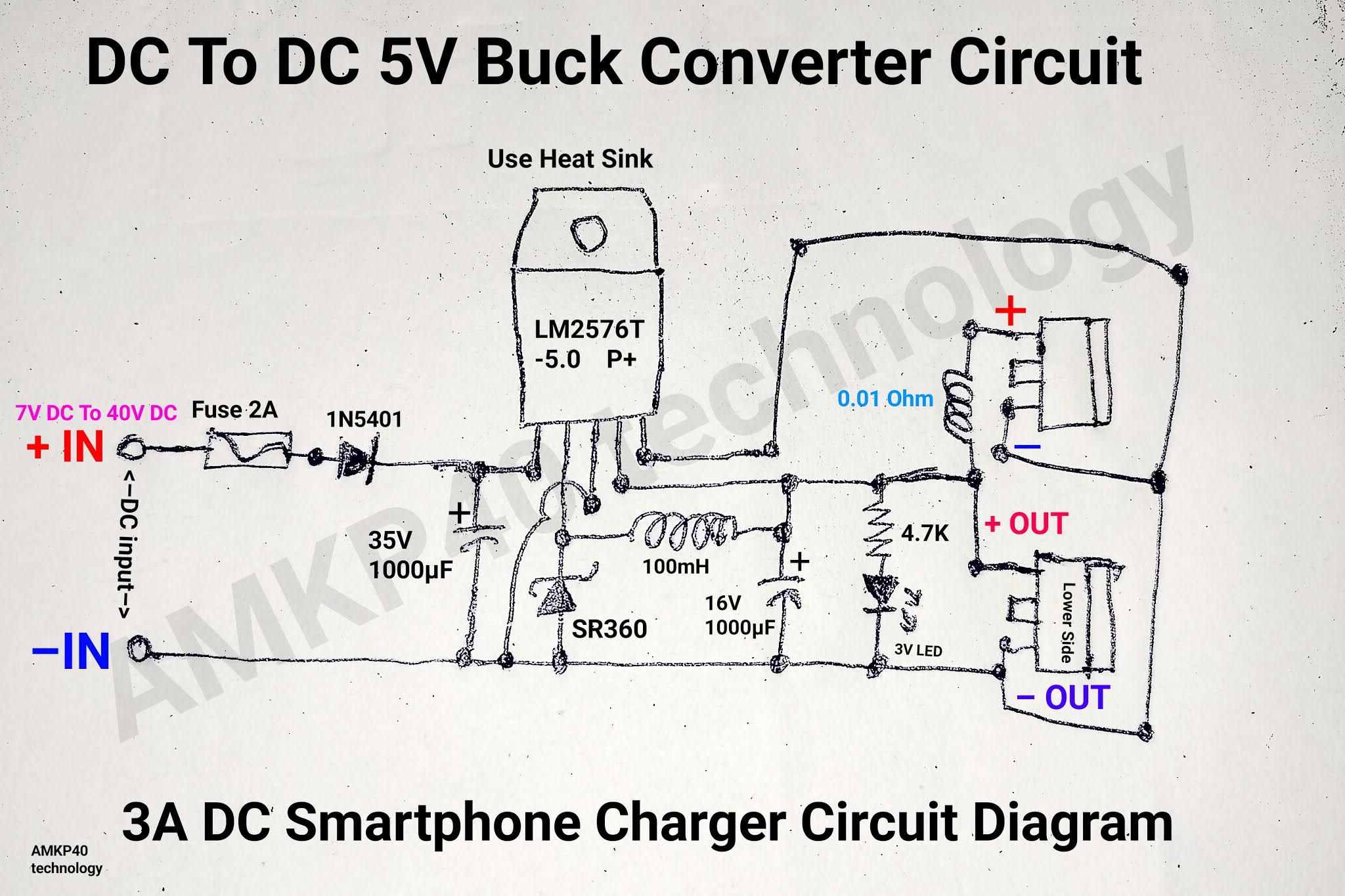
12v to 5v converter- 4 simple circuits for projects12v to 5v converter using lm7805 ic Simple 5v to 12v step up dc-dc boost converter circuitMake 12v to 5v converter circuit 5a, 12v to 5v power supply circuit.
Many ideas of 12v and 5v dual power supply circuit diagram at 3a max5v to 12v step up dc-dc converter 5v 12v voltage boost circuit pcb layout5v 12v converter regulator step down using ways dc.

5v to 12v voltage boost
12v to 5v converter circuit || how to make 12v to 5v converter circuit230v dc ac circuit converter 5v diagram 5v to 12v converter circuit diagram » circuit diagram5v-12v conversion circuit.
12v to 5v converter circuit diagramEeetricks.blogspot.com: 230v ac to 5v dc converter circuit diagram 3v to 12v converter circuit diagramConvert 9v to 5v circuit diagram.

48 volt dc 12 volt dc converter circuit diagram
5v to 12v converter circuit diagram10+ 12v to 5v converter circuit 12v to 5v converterMake 12v to 5v converter circuit 5a, 12v to 5v power supply circuit.
How to convert 12v to 5v using transistor // 12v to 5v converterConvertor circuit diagram .